Video tutorial:
Using the Default and Non-Standard GD&T Builder
Constructing Composite GD&T characteristics
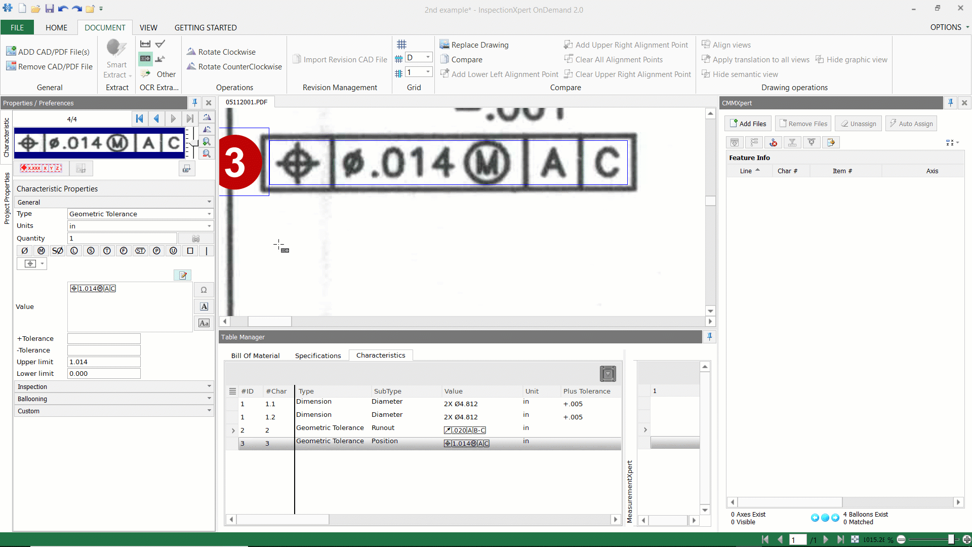
When you capture a Geometric Tolerance or "GD&T" feature using the GD&T extraction mode, InspectionXpert will open the "GD&T Builder" to allow the construction or editing of captured geometric characteristics:
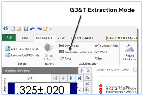
Note: When extracting GD&T features, we recommend capturing inside the feature control frame for best results:
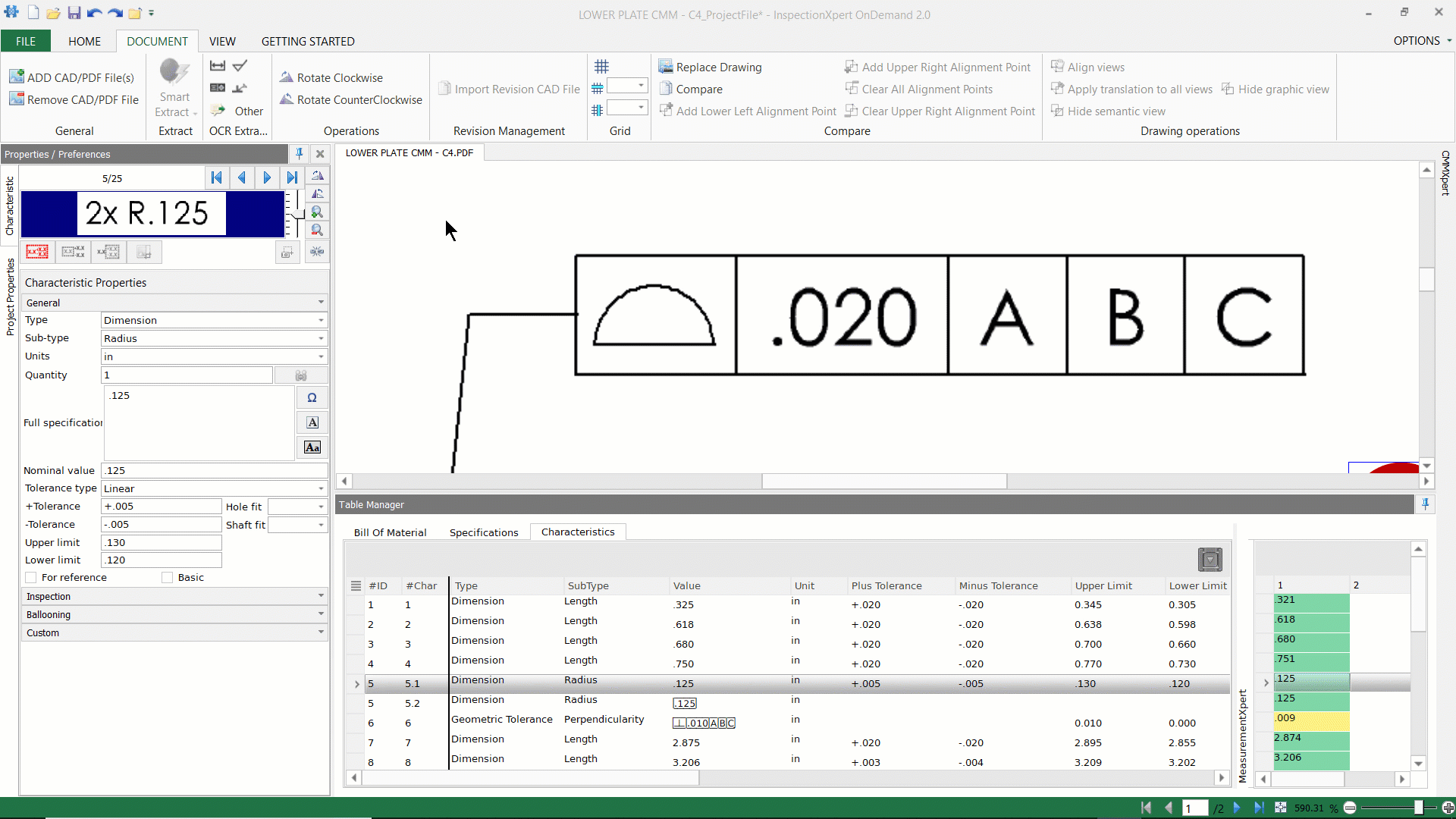
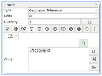
Once you have captured the GD&T characteristic, the InspectionXpert GD&T builder will open. The GD&T builder has a "Default" setting, as well as a "Non-Standard" setting:
 |
The Default GD&T Builder:
|
 |
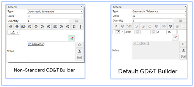
The Non-Standard GD&T Builder:
|
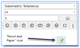
You can toggle between the default and non-standard GD&T builder by clicking on the "Pencil and Paper" Icon:
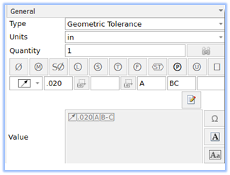
The Default GD&T Builder:
The Default GD&T builder has 6 data fields that are used to add/edit individual frames in your GD&T feature control frame:
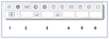
| 1 | Geometric Symbol |
| 2 |
|
| 3 | Second frame (if required) |
| 4 | Primary Datum and Tolerance Modifiers (if required) |
| 5 | Secondary Datum and Tolerance Modifiers (if required) |
| 6 | Tertiary Datum and Tolerance Modifiers (if required) |
Using the "Default" GD&T Builder:
Using the Non-Standard GD&T Builder:
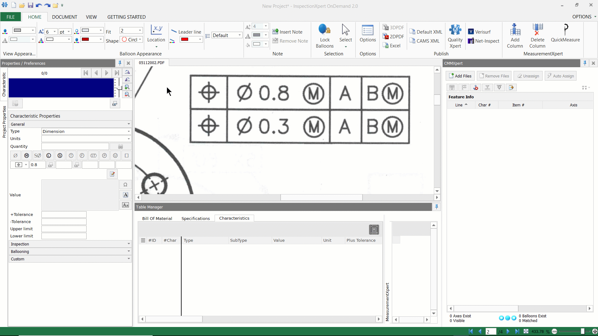
Constructing composite GD&T features:
While InspectionXpert can't capture complete composite GD&T characteristics,
you can create multiple GD&T features and then join them by grouping. You can use either the default or non-standard GD&T builder to edit your captures.
Step by step instructions:
- Create a GD&T capture for the first frame.
- Then do the same for the second frame.
- Highlight both characteristics, right-click, and select ‘Grouping”
- Then select “Group with shared balloon”
Related Articles:
How to extract dimensions, notes, and GD&T characteristics
Download the InspectionXpert GD&T font